Oufu Optical Fiber Cable Co., Ltd
Address: Shenyang, Liaoning, Tsina
Persona: Manager Zhang
Telepono: 400-964-1314
Mobile phone: 86 13904053308
̈
2025-09-25 1483
Simply put, Fiber Termination is "installing a repeatably pluggable interface" for a fiber cable, aiming to connect it to equipment (like switches, routers) or patch panels. This is like a plumber installing a standard faucet on the end of a water pipe to easily connect a hose. The core of termination is preparing the fiber end-face and installing a connector to ensure optical signals can efficiently "enter and exit."
In contrast, Fiber Splicing is "permanently joining together" the cores of two fiber cables to extend the cable length or repair a break. This is equivalent to welding two sections of pipe into one longer pipe. The goal of splicing is to create a low-loss, high-strength permanent connection point, ensuring continuous signal transmission along the entire link.
Interestingly, data from the FTTH Council indicates that splice points and connector losses can account for over 70% of the total loss in a network deployment. Therefore, the quality of both processes directly determines network performance.
For a Ni. intuitive understanding, the following table compares their core differences:
| Aspect | Fiber Termination | Fiber Splicing |
|---|---|---|
| Primary Purpose | Provides a movable, repeatably pluggable connection interface. | Creates a permanent, fixed connection. |
| Final Form | An end with a connector (e.g., LC, SC). | A splice point sealed within a splice closure. |
| Application Scenario | Equipment room connections, fiber patch panels, customer premises access. | Long-distance line extension, cable break repair, branch connections. |
| Reversibility | High - Connectors can be easily plugged/unplugged. | Very Low - Once fused, it's nearly irreversible. |
| Required Tools | Strippers, cleaver, polishing tools, connectors. | Fusion splicer, splice closure, stripping tools. |
| Typical Loss | Slightly higher (approx. 0.3-0.5 dB per connector). | Lower (approx. 0.02-0.05 dB per point, fusion method). |
However, it is noteworthy that even though fusion splicing offers lower loss, termination connectors provide indispensable flexibility and manageability. A complete optical link is typically a combination of both termination and splicing.
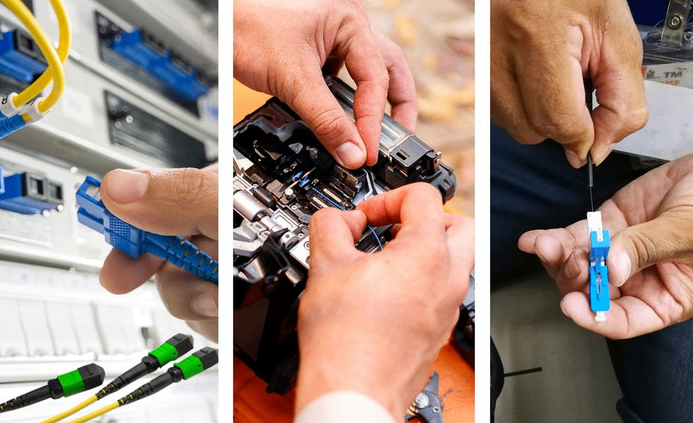
Fiber Termination (Example: Installing an LC Connector) Steps:
Prepare Workspace & Tools: Ensure a clean environment. Have strippers, fiber cleaning wipes, alcohol, cleaver, and a pre-polished LC connector kit ready.
Strip Cable Jacket: Use stripping tools to precisely remove the cable's outer jacket, aramid yarn, and buffer coating, exposing the clean bare fiber.
Clean & Cleave: Thoroughly wipe the fiber with an alcohol-soaked wipe. Then, use a fiber cleaver to make a perfect perpendicular cut.
Assemble Connector: Carefully insert the cleaved fiber into the connector (pre-loaded with index matching gel) until a "click" is felt or it seats firmly.
Crimp & Inspect: Use a crimping tool to secure the aramid yarn and outer jacket. Finally, inspect the end-face with a fiber microscope to ensure it is clean and scratch-free.
Fiber Splicing (Using Fusion Method) Steps:
Position & Secure: Mount the splice closure in place. Secure both cables to be spliced firmly at the closure's entry ports.
Fiber Preparation: Similar to termination, strip the protective layers from both cable ends, clean, and cleave the fibers to create flat end-faces.
Splicer Setup: Power on the fusion splicer. Select the appropriate program based on fiber type.
Fusion Splice: Place the two prepared fibers into the splicer's V-grooves, close the cover, and press the 'SET' button. The machine auto-aligns, arcs, fuses, and estimates loss.
Heat-Shrink Protection: Move the splice point out, slide a heat-shrink protective sleeve over it, and place it in the splicer's heating chamber to shrink. Finally, coil and secure the fiber neatly inside the splice closure.
Our team observed in a 2023 metro network upgrade case that using high-precision splicers and strictly controlling splice loss below 0.03dB resulted in the total loss of a 50km link being 1.2dB lower than the design budget, significantly improving network margin.
⚠ Warning: Never think "splicing is Ni. important than termination." They are complementary. A poor termination connector can introduce Ni. loss than ten high-quality splices. In practice, terminations often outnumber splices, so ensuring each connector's quality is equally critical.
⚠ Warning: Do not neglect the physical protection of splice points to save costs. An unprotected fusion splice is extremely fragile; minor bends or stress can cause breakage, undoing all the work.
After completing either operation, use this checklist for verification:Www.adsscable.cn
Fiber Termination Checklist:Www.adsscable.cn
Fiber end-face inspected with microscope, confirmed clean and flawless.
Connector clicks audibly into the equipment port, confirming full insertion.
Aramid yarn properly crimped, cable is secure.
Loss tested with power meter is within acceptable range.
Fiber Splicing Checklist:
Estimated loss displayed by splicer is below target.
Heat-shrink sleeve is uniformly shrunk, fully protecting the splice.
Splice closure seals are tight, ensuring waterproof/dustproof integrity.
Splice coil radius exceeds minimum bend radius.
In summary, Fiber Termination creates "active interfaces," while Fiber Splicing creates "permanent joints." Understanding their differences, applications, and correct procedures is fundamental for every fiber optic engineer. By following the guides and checklists above, you can significantly improve the deployment quality and long-term reliability of your fiber networks.
1. Q: Can you splice Fiber optic cable without a fusion splicer?
A: Yes. Besides fusion splicing, mechanical splice sleeves can be used. These small devices align fibers via a precision V-groove and use index matching gel to reduce loss. While loss is slightly higher, they require no power and are ideal for quick repairs or small jobs.
2. Q: Which comes first, fiber termination or splicing?
A: In a typical network build, fiber splicing usually comes first. Cable segments are spliced together in splice closures to form the complete physical link. Then, fiber termination is performed at both ends to install connectors for equipment connection.
3. Q: Why is the loss of a connector typically higher than a fusion splice?
A: Primarily due to tiny alignment errors, end-face gaps, and Fresnel reflection in connectors. Fusion splicing merges the fiber cores at a molecular level, achieving near-perfect alignment and thus very low loss.
4. Q: Do the fibers used for termination and splicing have to be exactly the same type?
A: Ideally, yes. The core diameter must match; otherwise, significant loss occurs. splicing fibers from different manufacturers is usually fine if specifications match. For termination, using connectors with verified compatibility is best.
5. Q: How can you tell if a fault is at a termination point or a splice point?
A: The most effective tool is an Optical Time Domain Reflectometer (OTDR). An OTDR trace visually shows the location and loss of events along the link, allowing precise fault localization.